Ads

Selasa, 10 Januari 2017

MENGHITUNG ARUS, DAYA DAN TORSI MOTOR LISTRIK

Cara menghitung kecepatan, arus, daya dan torsi motor listrik

Cara menghitung kecepatan sinkron jika yang diketahui frekuensi dan jumlah katupnya

Ns = (120.F)/P
Ns = kecepatan singkron motor dalam satuan rpm
Hasil gambar untuk motor listrikF = Frekuensi
P = jumlah kutub motor

Misalnya :
Kecepatan motor 4 poles/kutub
Frekuensi 50 Hz
Maka ns = (120.F)/P = (120.50)/4 = 1500 rpm

%slip = (ns – n) / ns X 100

Misalnya :
Kecepatan motor 1420 rpm engan kecepaan sinkron yang sama dengan hasil diatas maka
%slip = ((ns – n)/ns) x 100 = ((1500 – 1420)/1500) X 100 = 5%

Menghitung arus motor ketika diketahui daya (watt), tegangan dan faktor daya

P = V.I.cos φ dan I = P/V.cos φ
Misalnya :
Daya 1 kw, tegangan 220, dan faktor daya 0.88 berapa arus yang tradapat pada motor?
P = 1 kw = 1000 watt
I = P/V. cos φ =1000/(220.0.88) = 5 ampere

Menghitung daya motor listrik 3 fasa
P = 3 . v . I. cos φ  dan I =P/√3 . v . I. cos φ 
Misalnya :
Motor 3 fasa memiliki arus 9.5 ampere dengan tegangan 380V dan faktor daya cos φ = 0.88
P = 3 . v . I. cos φ  = 1.73 . 380 . 9.5 . 0.88 = 5495 watt = 5.5 kw

Efisiensi daya motor
 = P output/P X 100
Daya input motor 5 kw dan daya output 4.5 kw
5 kw = 5000 watt dan 4.5 kw = 4500 watt
ᶯ = (P out / P in) X 100% = (4500/5000)X100%= 90%

Menghitung Torsi motor

Menghitung torsi dengan diketahui daya motor dan kecepatan motor

HP = (T . n)/5250  dan   T = (5250 . HP) /n   dan  n = 5250 . HP/T
T = Torsi motor dalam tb tf
n = kecepatan putar motor (rpm)
HP = daya kuda motor(HP = 745 watt)
5250 = konstan

Misalnya :
10 HP kecepatan 1500 rpm
T = (5250 . HP)/n = (5250 . 10) 1500 = 35 lb ft = 45,6 Nm
T = F . D
T = torsi motor (dalam lb ft)
F = gaya (pon)
D = jarak (ft)

Itulah beberapa cara mengukur dan cara menghitung kecepatan, arus, daya dan torsi motor listrik AC. Semoga dapat bermanfaat dan dapat membantu masalah sobat.

menghitung ampere motor listrik dalam perhitungan elemen mesin

MENGHITUNG AMPERE MOTOR LISTRIK DALAM PERHITUNGAN ELEMEN MESIN

Sobat  yang baik hati, sekedar sharing saja , mungkin bagi anda yang belum tahu cara menghitung ampere beban pada listrik 3 (tiga) fhasa , disini kami akan memberikan rumus sederhana yang biasa di gunakan untuk menghitung Arus (ampere) pada beban listrik 3  fhase,.

berikut kami berikan contoh Cara menghitung Arus pada Motor Induksi AC 3 Fhase .

yang pertama,
 anda harus mengetahui tegangan beban yang anda gunakan .
contoh : tegangan  380 Vac 3 Fhase

yang kedua,
 Daya beban yang anda gunakan
contoh : Daya beban motor induksi 3 Fhase adalah 15 Kw (15.000 Watt )

dan yang perlu di perhatikan adalah COS Q beban, biasanya COS Q pada motor listrik 3 Fhase adalah 80~90 %
contoh : COS Q pada motor induksi 3 fhase adalah 85 %

Kesimpulan :

Rumus Penghitung Arus beban listrik 3 Fhase adalah :

I = P/ ( V x akar3 x COS Q )

I : Arus (ampere)
P : Daya (watt)

Jadi :

I= 15Kw / ( 380Vac x akar3 x 85% )

I= 15000 / (380 x 1,73 x 0,85 )
I= 15000/ 559
I= 26,8 A

Jadi arus beban motor induksi 15Kw adalah 26,8 Ampere


rumus ini juga biasa di gunakan untuk menentukan settingan thermal overload pada rangkaian panel motor induksi 3 fhase.

Sabtu, 07 Januari 2017

CALCULATION OF BASIC MECHANICS WITH LOADS ON BEAMS evenly SIMPLE

CALCULATION OF BASIC MECHANICS WITH LOADS ON BEAMS evenly SIMPLE

okay this time I will discuss one example of a distributed load on a beam calculation simple in pehitungan basic engineering mechanics.

Reinforced concrete beams measuring 300 mm x 500 mm is located at the top of the simple supported as shown in the image above .In the work load on the beam die plate (q_dpelat) = 2 kN / m 'and the burden of life (QL) = 2 kN / m'. If the weight of the concrete is calculated at 25 kN / m3, calculate the necessary torque and nominal moments for planning the block!

Completion !!
(A) Calculate the necessary torque beam (beam Mu)
Heavy beams = 0.3 x 0.5 x 25 = 3.75 kN / m '
Dead load:
The dead load = weight of the beam, (q_Dbalok) + Weight plate (q_Dpelat)

= 3.75 kN / m '+ 2.00 kN / m'

= 5.75 kN / m '

Moments due to dead load
MD (Moment Dead) = 1/8 * QD * L2 = 1/8 * 5.75 * 82 = 46 kn- m
Moment due to live load
ML (Moment of Life) = QL * 1/8 * 1/8 * L2 = 2 * 82 = 16 kn- m
Moment need beam (Mu)
MD mu = 1.2 + 1.6 ML

= 1.2 (46) + 1.6 (16)

= 80.8 kN-m

Mu calculate it another way:
Expenses need (qu) = 1.2 * QD + 1.6 * QL

= 1.2 * 5.75 + 1.6 * 2

= 10.1 kN / m '
The moment of need (Mu) = 1/8 * qu * L2

= 1/8 * qu * L2

= 80.8 kN-m

(B) Calculate the nominal torque Mn beam

in Learning about the beams and reinforced concrete slab (for beginners) already explained that a strong plan at least equal to a strong need to beam. Strong need has been calculated that Mu of 80.8 kN-m

Strong value plan = reduction factor kekutan * nominal compressive strength

So, the moment the plan (Mr) = the reduction factor kekutan * nominal moment (Mn)
According to the equation is obtained: Mr> or = Mu

If taken Mr = Mu = 80.8 KNM and power reduction factor for the (structure resist bending) = 0.80, the obtained

Mn = Mr / power reduction factor

= 80.8 / 0.8

= 101 KNM
Thus, Mn = 101 KNM

thanks for your atention and succesfull for you

COURSE MATERIALS AND METALLURGICAL ENGINEERING BASIC KNOWLEDGE

COURSE MATERIALS AND METALLURGICAL ENGINEERING BASIC KNOWLEDGE

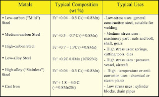
Material Classification Techniques:
Broadly speaking engineering materials can be classified into:
1. Material metal
2. Nonmetallic Materials

Based on the chemical composition of metals and alloys can be divided into two groups, namely:
1. Metal ferrous / ferrous
2. Metals non ferrous / non-ferrous

Ferrous metals are metals and alloys containing iron (Fe) as a main element.

Non-ferrous metals is a materiality that contain little or no iron. In the world of mechanical engineering, metals (mainly ferrous metals / steel) is the most widely used material, but other materials also can not be ignored. Non-metallic materials are often used because of the materiality has distinctive features that are not owned by the metal material.

Non-metallic materials can be divided into several categories, namely:
1. Ceramic
2. Plastic (polymer)
3. Composite
The ceramic material is a material formed from the compound (compound) between one or more metal elements (including Si and Ge) with one or more non-metallic elements. ceramic type material is increasingly being used, from a variety of abrasives, cutting chisel, refractory stone, glass, and others, even rocket technology and space flight is in need of ceramic.

Plastic (polymer) material is a result of human engineering, is a very long-chain molecules and molecules that bind to each other MER. The use of plastic is also very wide, from household appliances, car interior, cabinet radio / television, until construction machinery.

Composite material is the result of a combination of two or more materials, that is very different from the properties of each material origin. Composite addition is made of the results of human engineering, also can occur naturally, such as wood, which is composed of cellulose fibers which are in a matrix of lignin. Composites is currently widely used in aircraft construction, as have the nature of light, strong and non magnetic.

Mechanical properties are properties that express the ability of a material / component for receiving the load, force and energy without causing damage to materials / components.

Some important mechanical properties, among others:
1. Strength (strength)
Is the ability of a material to receive the voltage without causing material be broken. Based on the type of work load, the power is divided into several types namely tensile strength, shear strength, compressive strength, torsion strength and bending strength.

2. Rigidity (stiffness)
Is the ability of a material to receive the voltage / load without causing deformation or difleksi.

3. elasticity (elasticity)
Meterial defined as the ability to receive voltage without resulting in permanent deformation after the voltage is removed, or in other words the ability of a material to return to its original size and shape after being deformed (deformation).

4. plasticity (plasticity)
The ability of a material to undergo plastic deformation (permanent deformation) without sustaining damage. The material has high plasticity is said to be a resilient material (ductile), while materials having low plasticity of the material is said to be brittle (brittle).

5. Tenacity (ductility)
Is sutu material properties described bleak cable with a tensile strength applications. The ductile material must be strong and flexible. Tenacity is typically measured with a given period, the percentage of strain. This property is usually used in perteknikan midwives, and materials that have these properties include soft iron, copper, aluminum, nickel, etc.

6. toughness (toughness)
Is a material's ability to absorb some of the energy without causing any damage.

7. brittleness (brittleness)
Is a material that has properties opposite to ductility properties. This fragility is a rupture properties of a material with a slight shift permanent. The material is also fragile, subject to tensile load, without giving too much of strain. Examples of materials that have the properties of this fragility is cast iron.

8. Fatigue (fatigue)
Is the tendency of the metal to be broken when receiving alternating load (dynamic load), the amount is still well below the elastic stiffness.
 
9. stretchy (creep)
Is the tendency of a metal to plastic deformation when loading the relative magnitude is still being done in a long time at a high temperature.

10. Violence (hardness)
A material resistance to compression or indentation / penetration. This relates to the nature of wear resistant properties (wear resistance) is the resistance of a material to scratching or abrasion.

load
Defined as an external force that supports sutau part of the machine. The load consists of three types, namely:
 fixed expenses (steady load), said fixed load when the load

Jumat, 06 Januari 2017

PENGETAHUAN DASAR MEKANIKA TEKNIK

PENGETAHUAN DASAR MEKANIKA TEKNIK 

SALAM MACHINE BROTHER!!!!
kali ini saya akan membahas mengenai pengetahuan tentang mekanika teknik dasar yg sangat berkaitan erat dengan ilmu dalam teknik mesin.

A. Konsep Dasar 

            Cabang Ilmu Fisika yang berbicara tentang keadaan diam atau geraknya benda-benda yang mengalami kerja atau aksi gaya. Suatu kendaraan yang terletak di atas suatu jembatan. Beban Roda Pada Jembatan Tersebut adalah suatu beban atau gaya.
Gaya adalah sesuatu yang menyebabkan deformasi pada suatu struktur. Gaya mempunyai besaran dan arah, digambarkan dalam bentuk vektor yang arahnya ditunjukkan dgn anak-panah, sedangkan panjang vektor digunakan untuk menunjukkan besarannya.
Apabila terdapat bermacam-macam gaya bekerja pada suatu benda, maka gaya-gaya tersebut dapat digantikan oleh satu gaya yang memberi pengaruh sama seperti yang dihasilkan dari bermacam-macam gaya tersebut, yang disebut sebagai resultan gaya. Gaya adalah VEKTOR yang mempunyai besar dan arah. Penggambaranya biasanya Berupa Garis dengan panjang sesuai dengan skala yang di tentukan.


B. Macam Gaya Dalam ilmu analisis struktur, gaya dibagi menjadi 3 (tiga),


 diantaranya adalah sebagai berikut: 1. Gaya Koplanar adalah bila gaya-gaya bekerja dalam garis kerja yang satu bidang datar. 2. Gaya Konkuren adalah bila gaya-gaya yang kerjanya berpotongan pada sebuah titik. 3. Gaya Kolinier adalah bila gaya-gaya mempunyai garis kerja dalam satu garis lurus. Dalam Mekanika Teknik, hanya dibahas gaya yang terletak dalam satu bidang (Koplanar). 
Pada dasarnya gaya merupakan suatu beban yang memiliki berat atau satuan. Berdasarkan bebannya gaya dibagi menjadi 2 yaitu:
  1. Beban Titik
    Beban titik merupakan gaya yang bekerja pada sebuah bidang atau tumpuan, dimana luas bidang yang terpengaruh atau dikenai relatif kecil.
    misalnya; kolom, tekanan kaki meja, roda mobil, dan lain-lain.
  2. Beban Terbagi Rata
    Beban terbagi rata merupakan gaya yang bekerja pada suatu struktur atau bidang, dimana luas permukaan beban dan bidang yang terpengaruh relatif luas.
    contoh; balok sloof, pondasi, plat, dan lainnya.
Tumpuan merupakan suatu penyangga atau penahan konstruksi sebagai sistem untuk menahan gaya-gaya luar yang bekerja pada konstruksi tersebut.
Reaksi merupakan gaya atau perlawanan yang diberikan oleh tumpuan akibat adanya gaya aksi.


Contoh Soal #1
Contoh Soal #1

Hitung besarnya reaksi dari tumpuan diatas:
· ∑MA = 0
-RB . 10m + P . 5m = 0
-RB . 10m + 10 ton . 5m = 0
-RB . 10m + 50tm = 0
-RB . 10m = -50tm
RB = 5ton
· ∑MB = 0
RA . 10m – P . 5m = 0
RA . 10m – 10 ton . 5m = 0
RA . 10m – 50tm = 0
RA . 10m = 50tm
RA = 5ton
Kontrol :
RA + RB = P
5 ton + 5 ton = 10 ton
10 ton = 10 ton……………….OK!
Misalnya contoh soal 2


Conto Soal #2
Conto Soal #2

Hitunglah besarnya reaksi tumpuan A dan B?
Hitunglah besarnya reaksi tumpuan A dan B ?
∑H = 0
HA – P2. Cos 300 = 0
HA = P2 cos 300
HA = 1,5 . 0,866
HA = 1,299t
∑V = 0
= P1 + P2 sin 300
= 2t + 1,5 . 0,5
= 2,75 t
∑MA = 0
-RB . 8m + P1. sin 30 . 5m + P2 . 3m= 0
-RB . 8m + 1,5 t . 0,5 . 5m + 2t . 3m= 0
-RB . 8m + 3,75tm + 6tm= 0
-RB . 8m = -9,75tm
RB = 1,22ton
∑MB = 0
RA . 8m – P1 . 5m – P2. sin 30 . 3m = 0
RA . 8m – 2 t . 5m – 1,5t . 0,5 . 3m= 0
RA . 8m – 10tm – 2,25tm= 0
RA . 8m = 12,25tm
RA = 1,53ton
Kontrol : P1 + P2 . sin 300 = RA + RB
2t + 1,5 . 0,5 = 1,53 + 1,22
2,75 ton = 2,75 ton


jawaban soal #2
jawaban soal #2


C. Vektor Resultan 

Sejumlah gaya yang bekerja pada suatu struktur dapat direduksi menjadi satu resultan gaya, maka konsep ini dapat membantu di dalam menyederhanakan permasalahan. Menghitung resultan gaya tergantung dari jumlah dan arah dari gayagaya tersebut. Beberapa cara atau metode untuk menghitung resultan gaya, yaitu: 1. Metode penjumlahan dan pengurangan vektor gaya. 2. Metode segitiga dan segi-banyak vektor gaya. 3. Metode proyeksi vektor gaya. Untuk lebih jelasnya, berikut diuraikan masing-masing komponen tentang metode/cara untuk mencari resultan gaya. 


1. Metode penjumlahan dan pengurangan vektor gaya 

Metode ini menggunakan konsep bahwa dua gaya atau lebih yang terdapat pada garis kerja gaya yang sama (segaris) dapat langsung dijumlahkan (jika arah sama/searah) atau dikurangkan (jika arahnya berlawanan). 


Penjumlahan vektor searah dan segaris menjadi resultan gaya R


2. Metode segitiga dan segi-banyak vektor gaya 

Metode ini menggunakan konsep, jika gaya-gaya yang bekerja tidak segaris, maka dapat digunakan cara Paralellogram dan Segitiga Gaya. Metode tersebut cocok jika gaya-gayanya tidak banyak.  


Resultan dua vektor gaya yang tidak segaris.

Namun jika terdapat lebih dari dua gaya, maka harus disusun suatu segibanyak (poligon) gaya. Gaya-gaya kemudian disusun secara berturutan, mengikuti arah jarum jam.  

3. Metode segitiga dan segi-banyak vektor gaya

Resultan dari beberapa vektor gaya yang tidak searah

Jika telah terbentuk segi-banyak tertutup, maka penyelesaiannya adalah tidak ada resultan gaya atau resultan gaya sama dengan nol. Namun jika terbentuk segibanyak tidak tertutup, maka garis penutupnya adalah resultan gaya.

4. Metode proyeksi vektor gaya

 Metode proyeksi menggunakan konsep bahwa proyeksi resultan dari dua buah vektor gaya pada setiap sumbu adalah sama dengan jumlah aljabar proyeksi masing-masing komponennya pada sumbu yang sama. Sebagai contoh dapat dilihat pada Gambar dibawah ini.  
Proyeksi Sumbu

Xi dan X adalah masing-masing proyeksi gaya Fi dan R terhadap sumbu x. sedangkan Yi dan Y adalah masing-masing proyeksi gaya Fi dan R terhadap sumbu y. dimana Xi = Fi. Cos αi; X = R. cos αi; maka X = ΣXi Yi = Fi. Sin αi; Y = R. sin αi; maka Y = ΣYi.
        Dengan demikian metode tersebut sebenarnya tidak terbatas untuk dua buah vektor gaya, tetapi bisa lebih. Jika hanya diketahui vektor-vektor gaya dan akan dicari resultan gaya, maka dengan mengetahui jumlah kumulatif dari komponen proyeksi sumbu, yaitu X dan Y, maka dengan rumus pitagoras dapat dicari nilai resultan gaya (R), dimana: 2 2 R = X + Y dan Y X α = arc tan